DIPRO VridgeRDigital Manufacturing Tool
![]()
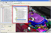
Key Features
Clipping
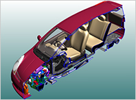
3D Clipping
Viewing the cut model allows you to review the internal structure.
It is also possible to use the slider to move the clipping plane position dynamically.
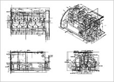
Section drawing
It is possible to clip at any position, easily create a section drawing, and add dimensions, notes, and 2D elements to the section drawing.
Dimensions and Measurement
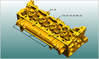
Dimensions
Measure coordinate values, distances, angles, and radii on a 3D model with the same level of precision as CAD, without referencing a drawing.
Mass Properties
It is possible to calculate surface area, weight, center of gravity, and so on.
Projected area
It is possible to measure the projected area, also to measure the maximum external box dimension from the projection direction.
Create trihedral figure
Automatically places top and right views relative to the viewing point.
It is possible to edit and re-register individual views in preview.
These view can be transferred to 2D CAD by outputting in 2D-DXF.
Disassembly / Assembly
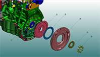
Exploded view
It is possible to create an exploded view easily by dragging the mouse.
Annotation
It is possible to create callouts and comments anywhere easily.
3D instruction manual
In combination with thumbnails and AVI output, you can create 3D instruction manuals.
Assembly Layout
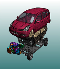
Layout
You can easily move and rotate each components or sub assembly by dragging the mouse.
Easily edit assembly structures imported from CAD.
Thumbnails
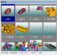
Thumbnails
A snap shot of current view can be registered as a thumbnail.
Select a registered view to see the previous scene.
Animation
Thumbnails can be displayed in any order, smoothly and continuously,
and can be used to verify tool trajectories, etc.
Documentation
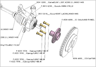
Illustration and high-precision hidden line processing
You can select the display and print mode according to your purpose.
You can paste an image of graphics to the clipboard.
Draft angle check
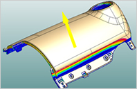
You can visually check if the part will come out of the mold.
By changing the draft angle and the draft direction, you can verify the pulling out from die.
Plate thickness
You can thicken sheet metal model. Even with complex sheet metal models, you can quickly and easily create thick faces.
VridgeR supports validation of sheet metal models.
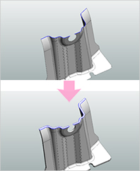
Geometry and Assembly comparison
Geometry comparison
The changed shape is colored and displayed.
This is useful when you are looking for changes due to design changes.
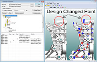
Assembly comparison
Compare each part and assembly configuration in the old and new data to detect changes in the old and new shapes, locations, and colors of the matching parts.
Interference and clearance check
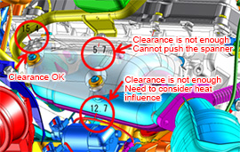
Even large assemblies with more than 1000 parts are immediately searched for problems. In addition, VridgeR support defect management and design review cooperatively by listing and outputting the problems found.
Dynamic interference check
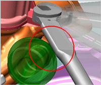
While moving a part, VridgeR dynamically checks for interference with other visible parts to visually check for interference conditions.
Process review
It is possible to review assembly process in a full assembly. Creates or edits a process sequence from an assembly structure or 3D geometry
Animation
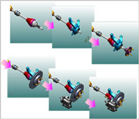
The assembly procedure of each part can be indicated in detail in 3D animation. It is possible to output the animation in AVI format.
Import points cloud
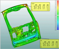
VridgeR allows geometry comparison between CAD data and measured high density mass point clouds. By displaying the error between the actual model and the digital model as a color map, you can efficiently check the quality.
Publish
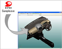
By sharing and running a "Publish" file that combines 3D data and viewing modules, anyone can view 3D data anywhere.
The image data shown are provided by Nissan Motor Co., Ltd. and the Japan Automobile Manufacturers Association.
DIPRO VridgeR is a trademark of DIGITAL PROCESS LTD.
All other product names are trademarks or registered trademarks of their respective owners.